
- Home
- Hot
- Products
- Application
- About Us
- Technical Guide
- News
- Contact Us
 English


A shear blade is an industrial cutting tool built to slice through metal plates and sheets. It applies localized mechanical force that exceeds the material's ultimate shear strength. Cutting efficiency and edge quality rely entirely on the contact point between the machine and the metal. Using an improperly specified blade causes premature wear, excessive burring, machine strain, and unplanned downtime. You need the right tool for the job. This guide breaks down the technical specifications, material compositions, and operational frameworks required to select, implement, and maintain the correct blade for specific metalworking applications. We look at edge geometry, steel grades, and clearance settings to help you optimize your shearing operations and prevent catastrophic tooling failure.
Material Dictates Performance: Selecting between high-carbon steels, shock-resisting tool steels, and hot work die steels depends strictly on the tensile strength and temperature of the material being cut.
Geometry Impacts Edge Quality: The choice between flat (90°) and beveled (82°) cutting edges directly influences the shearing force required and the risk of material distortion.
System Compatibility is Non-Negotiable: A hydraulic shear blade requires specific dimensional tolerances and clearance settings compared to mechanical or pneumatic shear systems.
The fundamental process of metal shearing relies on applying opposing forces to a material until it separates. This mechanical action does not happen instantly. It occurs in three distinct phases that dictate how the tooling interacts with the workpiece.
Plastic Deformation: The upper blade descends and makes initial contact with the metal. The material bends slightly and compresses under the heavy load, absorbing the initial shock of the machine ram.
Penetration: The blade cuts through roughly one-third of the material thickness. The exact depth of penetration depends heavily on the ductility and yield strength of the specific metal alloy being processed.
Fracture: The internal stress finally exceeds the shear strength of the metal. The remaining material fractures instantly, creating a clean break and separating the cut-off piece from the main sheet.
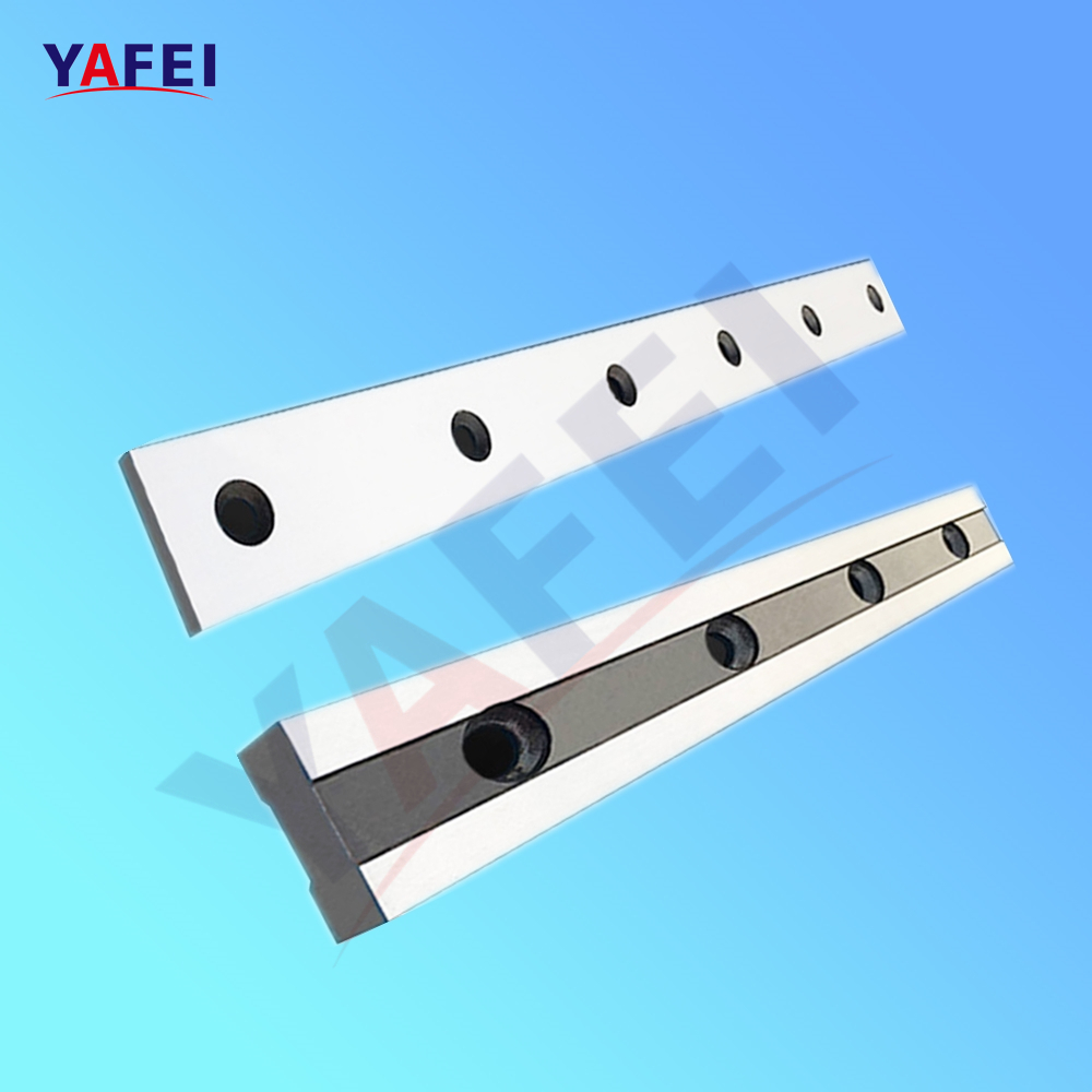
Understanding this sequence helps operators diagnose cut quality issues. Improper blade geometry or dull edges disrupt the transition from penetration to fracture, resulting in torn edges rather than clean cuts. A standard industrial blade consists of several critical components beyond just the cutting edge. Mounting holes secure the tooling to the machine ram and bed. These holes feature countersunk designs to keep heavy-duty bolt heads flush with the surface. Relief angles are ground into the back or sides of the blade. Proper relief angles prevent the tooling from binding against the freshly cut metal edge. This reduces friction during the downward stroke, minimizes heat generation, and prevents the machine from stalling under load.
Blade geometry dictates how force transfers into the workpiece. Manufacturers primarily utilize two edge profiles based on the thickness and type of material processed on the shop floor.
Flat (90°) Edges: These blades feature a square cutting edge. Operators use flat profiles for shearing heavier, thicker plates like AR400 or heavy structural steel. The 90-degree angle provides maximum structural integrity, preventing the edge from chipping or rolling under extreme tonnage. Flat edges require significantly more machine force to penetrate the material, demanding a high-capacity shear.
Beveled (82°) Edges: Beveled profiles incorporate a slight angle on the cutting edge. This geometry reduces the surface area contacting the metal initially, lowering the required shearing force. Facilities use beveled blades for thinner sheet metals, HVAC ducting, and aluminum. The reduced force minimizes material distortion, bowing, and twisting during the cut.
Edge Profile | Primary Application | Force Requirement | Edge Durability | Distortion Risk |
|---|---|---|---|---|
Flat (90°) | Thick plates, heavy structural steel | High | Maximum | Higher on thin sheets |
Beveled (82°) | Thin sheets, mild steel, aluminum | Low | Moderate | Minimal |
The rake angle refers to the incline of the upper blade relative to the lower stationary blade. Instead of striking the metal flat across its entire length, the upper blade contacts the material at an angle. It acts exactly like a pair of scissors. A higher rake angle reduces the tonnage required to make the cut. However, a steep angle increases the likelihood of the off-cut piece twisting or bowing. Operators must balance the rake angle against the machine's capacity and the desired flatness of the final product.
Clearance is the horizontal gap between the upper and lower blades as they pass each other. Setting the correct clearance is the most critical adjustment in any shearing operation. If the gap is too tight, the blades will collide, causing catastrophic tooling failure and potential damage to the machine frame. If the gap is too wide, the metal will fold or tear rather than shear cleanly. This leaves a heavy, jagged burr on the bottom edge of the cut. Clearance settings depend entirely on the thickness and tensile strength of the target material.
The metallurgical composition of metal shear blades determines their operational lifespan and failure modes. Selecting the wrong steel grade guarantees rapid edge degradation and constant machine downtime.
Grades such as D2, D3, D6, and Cr12MoV dominate standard cold shearing applications. These alloys contain high levels of carbon and chromium. During heat treatment, they form massive chromium carbides. This specific microstructure provides exceptional wear resistance, making them ideal for cutting mild steel, aluminum, and brass. The high carbide volume does reduce impact toughness. These blades perform poorly under heavy shock loads. They will chip if used to cut materials that exceed their rated capacity or if the machine operator drops heavy plate directly onto the cutting edge.
When operations involve cutting thicker plates, high-tensile steel, or heavy structural components, shock-resisting tool steels become necessary. The S-Series (like S7) and grades such as 6CrW2Si offer a different metallurgical balance. They contain lower carbon levels than D-series steels but incorporate silicon and tungsten. This composition absorbs massive impact forces without fracturing. The trade-off is reduced abrasion resistance. Operators will need to sharpen shock-resisting blades more frequently, but they avoid the risk of sudden, catastrophic edge failure during a heavy cut.
Hot shearing applications subject tooling to extreme thermal stress. Temperatures often exceed 800°C when cutting hot billets or forged components. Standard cold-work steels lose their hardness rapidly at these temperatures, turning soft and deforming instantly. Hot work die steels, including H13 and other H-Series alloys, contain molybdenum and vanadium. These elements allow the steel to retain its structural integrity and hardness at elevated temperatures. They resist thermal fatigue, preventing the formation of heat checks. Heat checks are microscopic surface cracks caused by rapid heating and cooling cycles during continuous hot shearing.
For facilities processing thinner, softer sheet metals in low-volume environments, premium high-alloy steels represent an unnecessary over-specification. Low-alloy tool steels like 9CrSi provide a practical alternative. They offer adequate hardness and edge retention for light-gauge mild steel and non-ferrous metals. These materials are easier to machine and heat-treat, making them highly accessible for general-purpose fabrication shops that do not run continuous production shifts.
Continuous, high-volume production environments demand tooling that can run for thousands of cycles without intervention. High-Speed Steel (HSS) maintains its edge significantly longer than standard tool steels, reducing the frequency of machine downtime for blade changes. For the most abrasive materials, such as electrical steel or high-silicon alloys, manufacturers utilize tungsten carbide inserts brazed onto a steel body. Carbide offers unmatched hardness and wear resistance but is extremely brittle. It requires rigid machine setups and perfect clearance settings to prevent the inserts from shattering under load.
Steel Grade | Primary Alloy Elements | Hardness (HRC) | Toughness | Best Application |
|---|---|---|---|---|
D2 / Cr12MoV | Carbon, Chromium | 58-62 | Low | Mild steel, aluminum, brass |
S7 / 6CrW2Si | Silicon, Tungsten | 54-58 | High | Thick plate, structural steel |
H13 | Molybdenum, Vanadium | 50-54 | Moderate | Hot shearing, billets |
9CrSi | Carbon, Silicon | 55-59 | Moderate | Light gauge sheet metal |
Tungsten Carbide | Tungsten, Carbon | 70+ | Very Low | Electrical steel, high volume |
The drive system of the shearing machine directly influences how force transfers into the tooling. A hydraulic shear blade operates under different mechanical realities compared to blades installed in mechanical or pneumatic systems.
Hydraulic shearing machines utilize fluid pressure to drive the ram downward. This creates a smooth, continuous, and controlled application of force. The blade pushes through the material steadily. Because hydraulic systems lack the sudden, violent impact of a mechanical flywheel, the tooling experiences less immediate shock. This allows operators to utilize harder, more wear-resistant blade materials that might otherwise chip in a mechanical shear. Mechanical shears rely on kinetic energy stored in a massive flywheel. The ram engages instantly, delivering a high-velocity impact. Blades for mechanical shears must prioritize impact toughness to survive the repeated shock loads.
Hydraulic systems demand strict dimensional accuracy from their tooling. The blade must meet exacting tolerances for parallelism and flatness, often measured in microns. If the blade thickness varies along its length, the clearance gap will fluctuate during the cut. This uneven gap forces the hydraulic cylinders to work harder in tight spots, straining the fluid system, blowing out seals, and damaging valves. Uniform cutting pressure requires perfectly ground blade surfaces from end to end.
To maximize tooling lifespan, manufacturers design blades with multiple cutting edges. The structural design of hydraulic blades often accommodates two-edge or four-edge reversible configurations. A four-edge blade features a rectangular cross-section where all four 90-degree corners act as cutting edges. When one edge dulls, maintenance personnel unbolt the blade, clean the seat, and rotate the tool to expose a fresh edge. This design extends the operational life of the tool by a factor of four before regrinding becomes necessary. Beveled blades typically only offer two usable edges due to their angled geometry.
Heavy industrial shears process large plates, but pneumatic air shears handle rapid, localized sheet metal cutting. These hand-held or bench-mounted systems utilize a completely different blade configuration. Air shears typically employ a three-piece blade set consisting of a right, center, and left blade. The center blade oscillates rapidly against the stationary side blades, removing a thin strip of material. This design allows for tight radius cuts and prevents the sheet metal from distorting. The metallurgical requirements for pneumatic blades focus heavily on fatigue resistance due to the high-frequency oscillation.
Selecting the correct tooling requires a systematic evaluation of the facility's specific cutting applications. Relying on guesswork leads to accelerated wear, poor cut quality, and rejected parts.
Calculate Maximum Tonnage: Determine the maximum tensile strength and thickness of the heaviest material you process. This establishes the baseline force the blade must withstand.
Assess Machine Capacity: Verify your shear can handle the required tonnage without deflecting the ram. A deflecting ram alters the clearance gap mid-cut, destroying the blade.
Select Edge Geometry: Choose flat edges for heavy plate steel and beveled edges for thin sheets to minimize distortion.
Determine Steel Grade: Match the blade metallurgy to the abrasion and impact levels of your daily production runs.
The primary factor in blade selection is the yield strength of the target material. Cutting mild steel requires different tooling than cutting stainless steel or titanium. Stainless steel work-hardens rapidly during the shearing process. As the blade penetrates, the stainless steel becomes harder, increasing the abrasive wear on the cutting edge. Shearing stainless steel demands high-alloy tool steels with maximum wear resistance. Cutting thick structural steel requires lower-hardness, high-toughness blades to prevent the edge from fracturing under the heavy load. You must calculate the required blade hardness based on the maximum tensile strength of the materials processed daily.
Industrial blades are consumable items designed for multiple lifecycles. When evaluating a blade profile, facilities must consider how many times the tool can be sharpened. Every regrinding process removes material, altering the overall dimensions of the blade. Eventually, the blade becomes too small to shim properly, and it falls out of the machine's acceptable tolerance range. Thicker blades with deeper mounting hole countersinks offer greater regrinding potential. Understanding the minimum allowable dimensions for a specific machine dictates how long a blade will remain in service before you must scrap it.
Facilities face a choice between purchasing replacement blades directly from the Original Equipment Manufacturer (OEM) or sourcing them from specialized aftermarket tooling engineers.
OEM Tooling: Purchasing from the machine builder guarantees exact dimensional fitment. The blades will match the machine's original specifications perfectly. OEM blades often utilize general-purpose steel grades designed to handle a wide variety of materials adequately, rather than excelling at one specific application.
Custom Aftermarket Tooling: Specialized blade manufacturers offer custom metallurgical solutions. If a facility cuts abrasive materials exclusively, an aftermarket engineer can specify a proprietary heat treatment or a specific high-alloy steel that outperforms the OEM blade. Aftermarket suppliers can grind custom relief angles tailored to solve specific binding or wear issues observed on your shop floor.
Proper installation and routine maintenance dictate the success of any shearing operation. Even the highest-quality blade will fail rapidly if installed incorrectly or neglected by the maintenance team.
Operators must recognize the physical indicators of a dull or damaged blade before it causes secondary damage to the machine. The most obvious sign is excessive burring on the bottom edge of the cut metal. A sharp blade leaves a clean, square edge. A dull blade drags the metal, creating a sharp, jagged burr. Loud, banging noises during the cut indicate that the machine is struggling to push dull edges through the material. Visual inspections often reveal micro-chipping along the cutting edge or a rounded profile where a sharp corner should exist. Any of these signs dictate immediate blade rotation or replacement.
Setting the blade gap is not a set-and-forget procedure. The clearance must change based on the material thickness being cut. The general industry standard dictates setting the clearance gap at 5% to 10% of the material thickness for mild steel. Cutting 0.250-inch mild steel requires a clearance gap of roughly 0.015 to 0.025 inches. Harder materials like stainless steel require a tighter gap closer to 5%. Softer materials like aluminum require a wider gap closer to 10% or 12%. Operators use precision feeler gauges to set this gap along the entire length of the machine bed, ensuring the distance remains consistent from end to end.
Replacing heavy industrial tooling presents significant safety risks. Maintenance personnel must follow strict protocols to prevent injury and machine damage.
Lockout/Tagout (LOTO): Completely isolate the machine from electrical, hydraulic, and pneumatic power sources. Block the ram physically with heavy timber or steel blocks to prevent gravity from causing an accidental descent.
Handling Heavy Tooling: Industrial blades weigh hundreds of pounds. Personnel must use overhead cranes, lifting straps, and specialized handling carts to maneuver the blades into position without dropping them or pinching fingers.
Cleaning Mounting Surfaces: Before installing the new blade, thoroughly clean the machine bed and ram seating surfaces with solvent and a wire brush. A single metal chip trapped behind the blade will cause it to bow. This destroys the clearance setting and can snap the blade during operation.
Torque Specifications: Tighten all mounting bolts to the manufacturer's exact torque specifications using a calibrated torque wrench. Uneven bolt tension causes blade distortion and localized stress points.
Following installation, operators must perform visual alignment checks. Slowly jog the ram downward manually or under low hydraulic pressure to verify that the upper and lower blades pass each other without making physical contact. Once visual clearance is confirmed, perform test cuts on scrap material. Measure the cut piece for squareness, check the edge for burrs, and listen for abnormal machine noise. Adjust the clearance gap as necessary based on the test cut results before resuming full production.
Preventing catastrophic blade failure requires strict operational discipline. Operators must keep the machine bed clean, removing cut-offs and debris that could jam between the blades. Never exceed the machine's rated capacity. Cutting material thicker or harder than the machine's specifications will fracture the blade or damage the hydraulic cylinders. Implement routine visual inspections at the start of every shift to catch micro-chipping or loose mounting bolts before they escalate into major failures.
Audit your current blade wear patterns to identify premature chipping or rolling.
Document the maximum tensile strength and thickness of materials processed daily to establish baseline tooling requirements.
Consult with tooling engineers to request material-specific metallurgical recommendations for your primary production runs.
Schedule planned maintenance downtime for comprehensive blade inspection and clearance calibration using precision feeler gauges.
A: Cutting stainless steel requires high-alloy tool steels like D2 or HSS. Stainless steel work-hardens during the cut, creating severe abrasive wear on the tooling. High-carbon, high-chrome steels provide the necessary wear resistance to maintain a sharp edge against these abrasive forces.
A: Frequency depends entirely on shift volume, material type, and blade configuration. A shop cutting mild steel on a single shift may run a blade for months. Facilities cutting abrasive materials continuously may need to rotate edges weekly. Four-edge reversible blades last significantly longer before requiring a regrind.
A: The general rule sets the clearance gap at 7% to 10% of the material thickness for mild steel. Harder metals like stainless steel require a tighter gap around 5%. Softer metals like aluminum require a wider gap up to 12% to prevent the metal from tearing.
A: No. Cold-work steels lose their hardness and structural integrity when exposed to high temperatures. Hot shearing applications require hot work die steels like H13 that contain molybdenum and vanadium to resist thermal fatigue and heat checking under extreme temperatures.
A: Chipping usually results from improper clearance settings, cutting material harder or thicker than the blade's rating, or using a blade with high hardness but low impact toughness. A loose mounting bolt can also cause misalignment, leading to blade collision and chipping.
A: Accurate replacement requires measuring the overall length, width, and thickness of the blade. You must also measure the hole spacing center-to-center, hole diameter, countersink depth, and identify whether the cutting edge is flat or beveled.


